AIRFIELD FACILITIES
Background –
Not all airfields are created equal. Some are on wide flat plains and others are stuck in a deep valley with mountains on both sides. Some are in densely packed cities and some are built on manmade islands in a body of water. Regardless of topography, all need to have an ‘Obstacle Clearance Zone’.
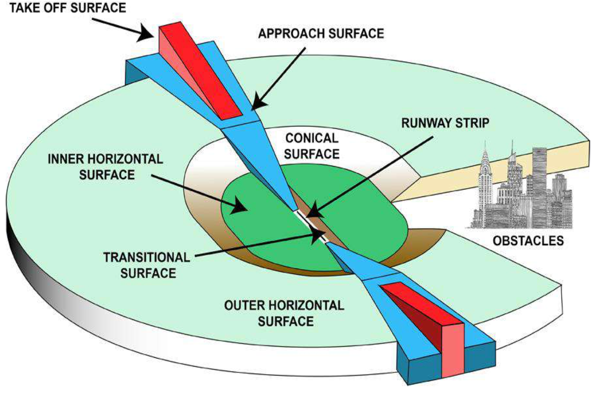
This is a zone centred over a runway that must be clear of obstacles apart from ‘frangible’ navigation aids such as ILS and Glide Slope antennae. This creates a protected path for the aircraft in both its landing and take off phases when close to the airport. An assessment is made of all obstacles in this area and the height of the tallest obstacle has an additional height added plus a ‘fudge factor’ to account for the aircraft type and airfield (big heavy vs small prop/narrow vs wide runway etc) This forms what is known as the OCH or Obstacle Clearance Height. It is from this OCH that airports and aviation authorities via set out procedure design criteria can create what is known as approach Minima or the stated visibility and altitude or height that an aircraft is allowed to operate in and down to before a landing is not allowed. As this guide is about low visibility we will focus on ILS or Instrument Landing System procedures.
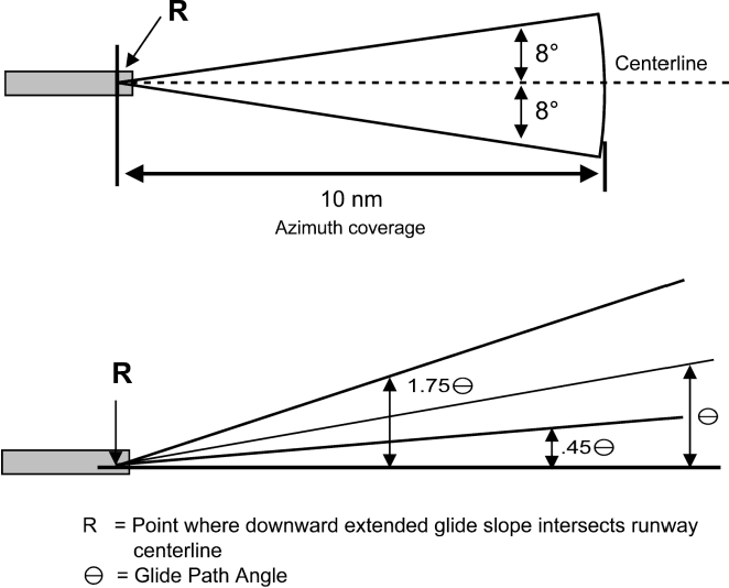
An ILS provides precision guidance and a 3D approach (both lateral and vertical guidance are externally provided to guide the aircraft) down to either a Decision Altitude (DA) or a Decision Height (DH). DA is referenced to mean sea level and DH to the height above the landing runway threshold.
For a clear day or one where the cloud base is greater than 200ft off the runway and the visibility greater than 550m generally, we can fly down to a CAT 1 minima that would normally require 550m visibility and allow us to descend to an altitude 200 ft above the runway. We can do this based on a pressure altimeter.
The next few categories below a CAT 1 ILS approach place us into the realms of low visibility and we need a radio altimeter to go to a lower height.
Runway Requirements –
In order to fly anything other than a simple approach in clear, calm, benign weather conditions we need to have sufficient lighting in order to be able to firstly see the runway when we arrive at the lowest permitted height, and secondly to know where abouts we are in relation to that runway.
A difference in the type of lighting found at a small quiet airfield vs a large international capable of supporting and executing low visibility operations is seen below
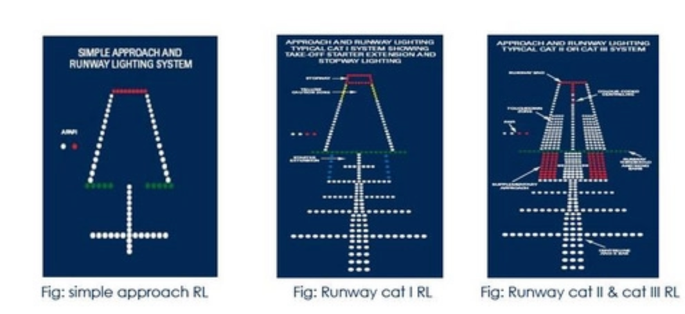
As you can see, for approach and landing CAT II and CAT III operations in low visibility we need a lot more lighting. We need to have;
RUNWAY EDGE LIGHTING – they mark the side edges of the runway, are white and need to be spaced no greater than 60m apart. 600m or a 1/3 of the runway distance from the end and these lights may be coloured yellow.
RUNWAY END LIGHTS – they are coloured red and aimed towards the landing direction and mark the end of the Landing Distance Available, there must be at least 6 of them spaced no more than 6m apart.
THRESHOLD LIGHTS – Spaced at 3m apart they are green and displayed at the very beginning of the threshold in the direction of landing.
TOUCHDOWN ZONE LIGHTS – these extend in two rows of barrettes into the runway beyond the Threshold lights and sat either side of the runway centre line. These are a specific requirement for CAT II and CAT III ops. They are formed of 3 lights spaced 1.5m apart max and each set are between 18 – 22m apart dependant on runway width. They will travel along the runway for 900m and the spacing for each pair needs to be 30 or 60m with 30m enabling a lower set of values to be used for height and visibility for landing aircraft.
CENTRE LINE LIGHTING – a typical feature of most runways, but for these operations it needs to be colour coded. At 900m from the end of the runway it alternates between red and white, and with 300M to go until the runway end lights, the centre line lights are all red.
RETILS – Rapid exit taxiway indictor lights a 3 sets of lights that are arranged 3 then a pair or 2 and then a single light that marks the start of the turn off lights (think motorway exit countdown markers). These taxi way lights that lead off the runway will be alternating yellow and green whilst we are in the ILS CRITCAL AREA.
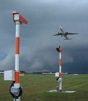
RUNWAY VISUAL RANGE TRANSMISSOMETERS – These are devices that measure the visibility and are placed to the side of the runway shoulder at the touchdown, mid-point and stop end of the runway and are permanent fixtures.
 Taxiway Requirements
 –
The lighting and marker boards which will be illuminated are seen below.
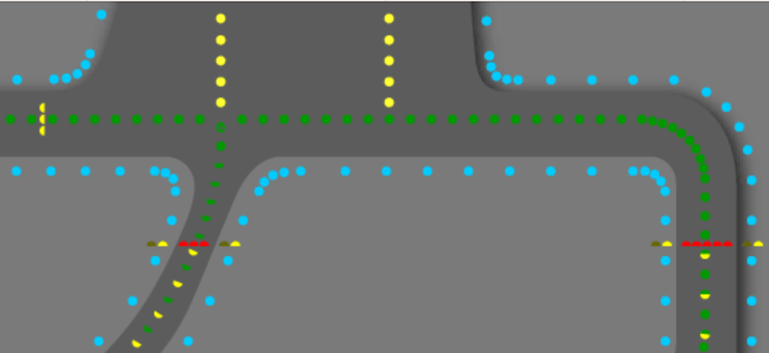
Essentially the green centreline lights will be spaced no more than 30m apart and even as close at 7m at junctions and corners. There will be blue taxiway edge lighting and as we approach the ILS CRITCAL AREA there will be a switch to alternating yellow and green centreline lights.
The runway entrance will be guarded by signage, and for CAT II and III there will be a sting of what look like roman numeral 2s or IIs. This I further enhanced by yellow flashing ‘wig-wams’ by the taxiway sides and possibly inset flashing yellows either side of the taxi way centre line. In the USA there are also red lights to ‘block’ your path that are controlled automatically by ground radar sensing aircraft on or approaching runways.
ILS CRITCAL AREA – The operation down to CAT II can result in either a manual landing (with specific training) or an Autoland. ALL CAT III approaches must end up with an Autoland. In order for this to be safe the ILS signal which is guiding the aircraft must be protected. Metallic objects such as ground vehicles and aircraft can bend, and deflect this signal which can affect the following aircraft’s approach.
To prevent this nothing other than an aircraft landing must be anywhere near the runway and ILS CRITICAL AREA that extends either side of the runway shoulders. This is the significance of the yellow and green alternating centreline lighting. It marks the ILS Sensitive area. And is protected three fold. Firstly pilots will vacate safely and report runway vacated once the tail is clear of this area, this signals that we will no longer be affecting the following aircraft’s takeoff roll or Autoland.
The ground roads will have stop signs, marker boards and warning symbols to alert ground based vehicles and usually Airfield Ops of the airport will be ensuring CAT III safeguarding to ensure the critical and sensitive areas are sterile.
This CAT III safeguarding forms part of Low Visibility Procedures conducted and executed by the airport and ATC. It is promulgated in many ways buy the decision to enter the procedures is normally based on visibility alone and sometimes cloud base, airfield dependant. As an example for Heathrow the criteria are either the runway visual range is 1000M and expected to fall to 600M or the cloud base is at 300ft and expected to fall to 200ft.
For Airfield Ops it is a case of ensuing road signs are working and appropriate lighting functioning and to monitor for any possible infringements of critical and sensitive areas. For ATC the approach controllers will be needing to increase the spacing on the approach between aircraft to ensure a sufficient gap for the preceding aircraft to vacate and no longer be interfering with the ILS signals prior to the following aircraft getting to a critical height. All operators and ground staff will be made aware of the safeguarding procedures commencing and that the airfield is entering low visibility procedures. Once the safeguarding is completed, ATC is notified and only then may ‘Low Visibility Procedures’ commence.
This at capacity constrained airports is what leads to delays for inbound aircraft. For forecast low visibility conditions London ATC will proactively set via eurocontrol a ‘flowrate reduction’. This maybe down to half of the normal rate in which Heathrow, Gatwick, Stanstead et al land aircraft on a lovely day. Those aircraft already airborn will be told to slow down in order to reduce the amount of time they are holding in the holding patterns prior to commencing their approach. To prevent a log jam, these not already departed will have a delay placed on their flight. Dependant of forecast severity and duration, some flights may also be pre-emptively cancelled.
Fog is however a tricky mistress to play with and it can persist or dissipate out of forecast expectations. As soon as the flow rate can be increased ATC will want to open the tap as quickly as it can in order to prevent further dieback of log jammed aircraft. It is for this reason you find yourself boarding more or less on time and then being sat there waiting. ATC need to know that the second they say ‘’go’ that you are ready to react promptly.
The only other real pressing issue is the ILS itself which much be calibrated at regular intervals and have an immediate power back up supply capable of taking over instantly should the primary power source fail.